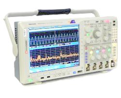
Tektronix MDO4000B Series calibration and repair
Have your Tektronix equipment calibrated in the ISO/IEC 17025 accredited lab!
Minerva is specialized in repair and calibration services of Tektronix instruments. These Tektronix instruments are calibrated in a ISO/IEC 17025 accredited calibration lab.
The calibration is performed by calibration technicians. We have more then 30 years of experience in calibrating instruments. In short, your Tektronix instrument is taken good care off! We focus on a fast lead time and extremely high standard of our service.
Tektronix MDO4000B Series Mixed Domain Oscilloscopes
applies to: MDO4014B 3, MDO4034B 3, MDO4054B 3, MDO4054B 6, MDO4104B 3, MDO4104B 6
Introducing the world’s first oscilloscope that includes a logic analyzer, spectrum analyzer and protocol analyzer – all synchronized for an
integrated view. Although you can use the MDO4000B Series simply as a mixed signal oscilloscope or as a spectrum analyzer, the real power comes from the integration of the two. For the first time ever, you can see how your designs perform in both the time and frequency domains on a single instrument. View the RF spectrum at any point in time to see how it changes over time or with device state. Solve the most complicated design issues, quickly and efficiently, with an oscilloscope as integrated as your design
Key performance specifications:
4 analog channels
1 GHz, 500 MHz, 350 MHz, and 100 MHz bandwidth models
Up to 20 M record length on all channels
>340,000 wfm/s maximum waveform capture rate
16 digital channelsresolution
MagniVu™ high-speed acquisition provides 60.6 ps fine timing 1 spectrum analyzer channel
9 kHz to 3 GHz or 9 kHz to 6 GHz frequency range models
Ultra-wide capture bandwidth ≥1 GHz
Standard passive voltage probes with 3.9 pF capacitive loading and 500 MHz or 1 GHz analog bandwidth
Key features
Mixed signal design and analysis
Automated triggering, decode, and search on serial and parallel buses
Per-channel threshold settings
Multichannel setup and hold triggering
Spectral analysis
Dedicated front-panel controls for commonly performed tasks
Automated peak markers identify frequency and amplitude of spectrum peaks
Manual markers
Trace types include: Normal, Average, Max Hold, and Min Hold
Detection types include: +Peak, -Peak, Average, and Sample
Spectrogram display for insight into slowly changing RF phenomena
Automated measurements include: Channel Power, Adjacent
Channel Power Ratio (ACPR), and Occupied Bandwidth (OBW)
Trigger on RF power level
Mixed-domain and analysis
Time-correlated analog, digital, and RF signal acquisitions in a single instrument
Wave Inspector® controls provide easy navigation of time correlated data from both the time and frequency domains
Amplitude, frequency, and phase vs. time waveforms derived from spectrum analyzer input
Selectable spectrum time to see how RF spectrum changes over time even on a stopped acquisition

